TEC-1
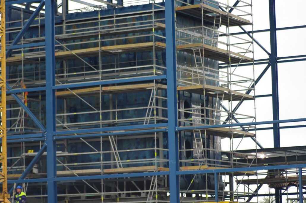
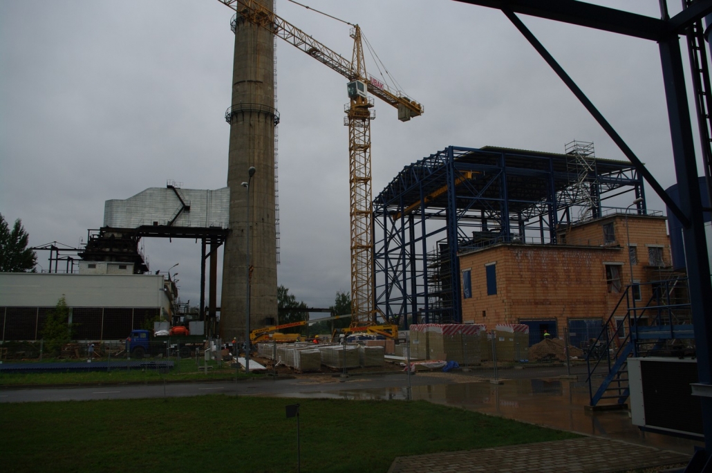
This project has been accomplished as a part of another project that envisaged the modernization of outdated steam power plant TEC-1 in Riga, Latvia, aiming at the building of a new plant and a gradual decommissioning of the old one.
This project has been accomplished as a part of another project that envisaged the modernization of outdated steam power plant TEC-1 in Riga, Latvia, aiming at the building of a new plant and a gradual decommissioning of the old one.
This project has been accomplished as a part of another project that envisaged the modernization of outdated steam power plant TEC-1 in Riga, Latvia, aiming at the building of a new plant and a gradual decommissioning of the old one.
The new complex would consist of a cogeneration plant including also two power turbines, one steam turbine and two water boilers with a capacity of 116 MW per each with added network pumps.
The goal of this project was a complete automation of water boilers and their service equipment; a creation of local control and organization of data exchange with a control system of the cogeneration plant in order to provide a remote control opportunity.
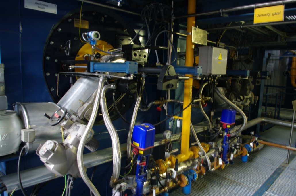
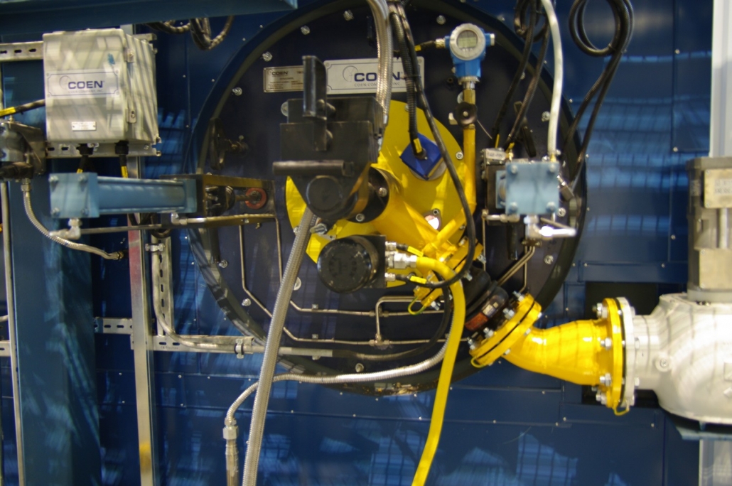
The equipment of the Boiler House consists of two water boilers KVGM-100 with four combined burners (gas, oil fuel), also a water cycling system and supporting facilities.
As the goal of this project was an automation of large heat-supply system, there were high reliability and fault tolerance requirements set for this assignment as the object of automation was the second biggest by its capacity in Riga. A special attention was also paid to the operational safety issues as potentially dangerous substances have been used for a boilers operation.
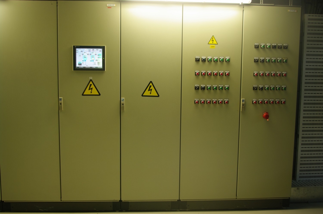
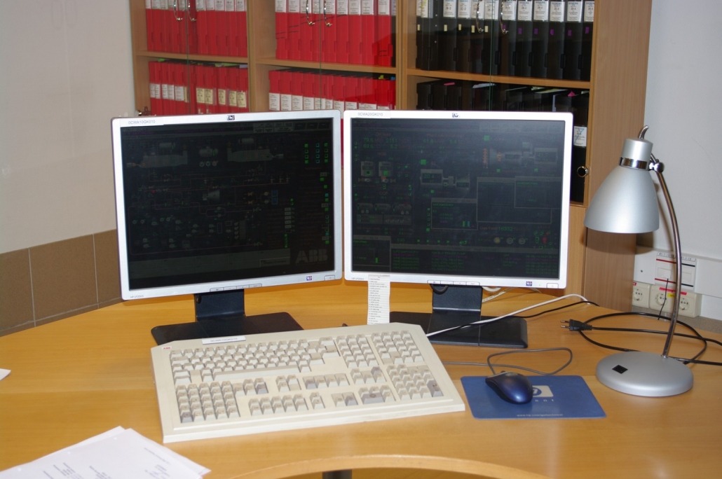
In order to provide a high reliability and unification of the automated equipment of power part of the plant, a decision was taken to use controllers ABB AC 160 and graphic panels Telemecanique Magelis XBT GT 6000-Series as a local control system. A connection to the control system of cogenerated facility based on controllers ABB AC 450 and the visualisation system ABB Advant Station 500 was organized through busbar AF-100.
Control system consists of three main parts: Boiler No 1, Boiler No 2, Common Equipment
A separate controller is responsible for each mentioned part. All controllers are linked through the busbar AF-100 which provides the data exchange process.
Automation of burning process is implemented separately for each burner of the boiler by an independent scheme with using components manufactured by DURAG Group (Germany).
Burners of the boilers are controlled by pairs, as boilers can function either in the constant power mode or constant temperature one. The system can control the water consumption delivered into the network or the pressure of the power conduit independently of boilers operation mode.
According to the test results the following parameters of the boilers system operation were drawn out:
Heat load range: 11.6-232 MW (stepless)
Water output temperature: 60 – 150 C
Water consumption via Boiler house: 50 – 6000 m3/h
Atmosphere pollution: NOx < 150 mg/m3
CO < 100 mg/m3
During the operation of the modernized TEC-1, Riga, Latvia, a need appeared for a backup boiler house to secure the supply of heat power into the network of Rigas Siltums/ Riga Heat enterprise that is the main heat supplier on the territory of Riga city.
During an implementation of this project, an additional boiler house was developed on TEC-1 consisting of the third boiler, 116MW, and a pump unit. The new boiler house is located in a separate building and can be operated in two ways: as an individual system, independent of the main boiler house, or as a consisting part of the whole boiler house; in that case the new boiler is operated together with the two existing boilers and pumps are included into the system of the main pumping unit.
The current scheme has been carried out to improve reliability of the boiler house – even in the failure of any facilities partly or fully stopping the operation of the whole boiler house, there is still an option to turn it off-line and operate the new boiler unit. At the same time, an operation in a shared mode enables an automatic loading distribution of the boilers as well as the water flow rate.
A control of the new boiler unit can be carried out by a local control panel or by the central control panel. The control system has been divided into the following components: Boiler No 3, Proofing of boiler No 3, Facilities of the boiler houses, Facility proofing of the boiler houses
To control the most important parameters of the boiler house and secure proofing functions, specific controllers Siemens Simatic and combustion control modules DURAG have been utilized. In order to unify the automation system with already installed system of boiler and general equipment control, ABB AC160 controllers have been implemented.
Our home page has already informed about the modernization project of Riga Steam Power Plant TEC-1 where we have taken part. The purpose of this account is to present a slightly more expanded concept of technology implemented in automation systems of heating boilers unit of the plant. A detailed description would certainly take many pages and unlikely appeal to a majority of readers, therefore only the basic principles have been presented hereinafter. Those of you who would need a more detailed account, please see a list of contacts in Contacts section of the page.
Boiler houses of Riga TEC-1 are highly automated and integrated systems that are operated without any manual intervention to maintain the required parameters of various systems and to start the facilities. As it was mentioned in the account of projects, there are two boiler houses on TEC-1.
1) A central one, that consists of two water boilers – 116MW each, a pumping unit including three pumps and a supply line to ensure the minimum pump circulation, a boiler bypass.
2) A supplementary one consisting of a boiler, 116MW, a pumping unit including two pumps and a supply line to ensure the minimum pump circulation, a boiler bypass and a connection line to the main boiler.
Each boiler is equipped with an air injection fan, exhauster, recirculation pump, a set of valves and adjusters, four bi-combustible burners (gas or diesel).
The automation system of the boiler houses is divided into parts – a control of a certain boiler and its operational equipment (separately for each boiler); a control of all facilities of a corresponding boiler house (separately for the central and supplementary boiler house).
Automated control system of the boiler supports the required water parameters, such as:
1) The minimum boiler circulation to ensure safety of its water pipes from overheating.
2) Boiler’s output pressure – a protection from the inner steam generation.
3) Temperature of the boiler’s inlet point (following ignition and reaching the desired temperature at the outlet point) – protection against condensation.
Besides, it provides automatic parameters required to set the desired boiler capacity on a particular moment and ensuring a safe and the most efficient fuel combustion:
1) A pressure inside the air supply panel of the burners (varies according to capacity settings), fine adjustment of the combustion stability as well as reduction of boiler emissions.
2) Furnace exhaustion (including the maximum workout at the ignition during an inevitable upsurge).
3) Combustible pressure in front of the burners (gas or diesel fuel).
The automation system of the boiler houses provides the required water parameters as well as supports, with the help of the pump unit, the necessary pressure at the boiler outlet depending on a current situation or the overall consumption of the boiler house; besides it can limit a boiler consumption by a cool bypass of the boiler house, securing a minimum consumption rate via the pump unit. The main task of the boiler house control panel is to maintain the desired temperature at the network output achieving that by adjustment of the boiler loading and water distribution.
As it has been previously described in the acount of this project, the supplementary boiler unit of TEC-1 is able to operate both ways – completely autonomous or combined with the central boiler house unit.
Switching from one mode to another with a corresponding change of control logic and methods of load and water distribution is automatic and only requires an operator to insert the closure command of end fittings.
In a shared mode the main controller of the central boiler house operates three boilers and five pumps as a single unit, deactivating a supply line ensuring the minimum consumption of the pump unit and a bypass of the supplementary boiler house. All operating boilers are aligned according to their loads and consumption despite the diferences in hydraulics.
If necessary, an operator can manually set a loading of a specific boiler, in that case any excess of the required total loading is distributed via boilers which are operated automatically.
In the case of autonomous mode of the supplementary boiler house, general controllers of the boiler houses operate independently, each maintaining its own temperature parameters and water settings – the pressure or consumption.
Power connection of boiler houses (regardless of the supplementary boiler house mode), ignition of the boiler, its halting and network disconnection takes place automatically on both boiler houses. Fully automatic power connection of the stopped boiler house takes less than 15 minutes, a startup of a boiler – further 15 minutes, respectively, an operator is able to operate the boiler within 30 minutes when required, and the boiler is completely ready to be set the required loading parameters.
In case of extinction of one or more burners, a corresponding boiler keeps operating on the remaining burners, though without any option to increase its loading. After an operator has inserted a command of reducing the boiler’s loading and reaching parameters suitable for burner ignition, a boiler restarts automatically and is available again for a full range operation. While on standby waiting for an operator’s command, this case may result in a possibility of restarting the supplementary boiler and minimizes the effect of temporary capacity loss.
Regardless of the operating mode, automated control system operates potentially dangerous parameters of boilers (pressure of water, air, combustibles; water flow rate, furnace exhaustion, water temperature, a critical failure of main sensors, flame lift-off from burners), as well as boiler houses (water pressure at various points, gas leakage, sensor failure, ventilation system breakdown) and in case of a hazardous situation operates correspondingly.


![]()
Our company has implemented assignments based on equipment of different manufacturers.